Controls
Gains and Display
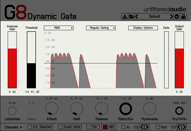
Analysis Gain: Controls the amount of gain applied to the analyzed audio signal. The analyzed signal is considered separately from the outgoing signal in G8. Because of this, this control does not affect the amplitude of the signal that you can hear.
Threshold: Controls the level of the gate’s threshold. When this threshold is exceeded by the amplitude of the incoming audio, the gate will open and allow the audio to pass through. When the incoming audio is below the threshold value on the other hand, the gate will close.
Gate Meter: A non-interactive component that displays the current value of the gate envelope. If you would like to see a more detailed history of the envelope’s value, you can click the “Display Options” button and enable the “Show Gate” parameter, which will then add the envelope to the waveform display.
Output Gain: Controls the amount of gain applied to the outgoing signal from G8. This gain does not affect the analysis levels of the incoming audio.
RMS/Peak: Selects the analysis type. Use “Peak” for more rapid analysis of signals with many transients (i.e. percussive signals).
Behavior Mode: Selects the behavior of the gate envelope. Choose between “Regular Gating”, “One Shot”, and “Cycle”. Please see the section on “Alternate Gate Behaviors” for more info.
Display Options: Provides a menu to enable or disable the entire waveform display, or individual components of the waveform display. The three options can each be enabled/disabled individually:
- Show Input (Gray): Shows the input signal used to compare to the threshold value during analysis.
- Show Output (Red): Shows the output signal after the gating has been applied.
- Show Gate (Black): Shows the normalized gating envelope as it is applied to the incoming signal.
Gate Controls
Attack: Controls the amount of time it takes for the gate to open to maximum amplitude after the incoming audio goes above the threshold. Extremely short values (< ~10 ms) can result in clicks, due to the rapid change in amplitude.
Hold: Controls the amount of time that the gate is required to stay at maximum amplitude for. If the incoming audio drops below the hysteresis point before the hold stage is finished, the hold stage will complete before the release stage begins.
Release: Controls the amount of time that it takes for the gate to go from maximum amplitude to minimum amplitude. This stage occurs after the incoming audio drops below hysteresis, and after the hold stage is completed.
Reduction: Controls the amount of gain removed from the audio signal when the gate is closed. This effectively sets a minimum amplitude for the gate envelope.
Hysteresis: Controls the hysteresis point, often referred to as the “bottom threshold”. The audio signal must drop below this bottom threshold before the gate can close.
Dry/Wet: Controls the balance between the “dry” (unaffected) incoming signal, and the “wet” (affected) outgoing signal. Please keep in mind that the “dry” signal is delayed by the Lookahead value, meaning that it is not a truly bypassed signal. This was done so that the wet and dry signals maintain the same phase.
Lookahead: Delays the signal by a chosen amount to allow the gate’s analysis stage to better predict incoming transients.
Delay: This control is only active when “Cycle” mode is selected (Please see the section on “Alternate Gate Behaviors”). Controls the length of silence inserted between envelope cycles.
Advanced Controls (Bottom Left)
Channels Display: Displays how many channels your host currently supports. This number is equal to the number of input channels. You can use this for troubleshooting your setup.
Expert Mode: Toggles whether or not Expert Mode is active. For more information, please see the section on “Expert Mode”.
Flip Mode: Toggles whether the primary outputs and reject outputs are swapped. For more information and techniques, check out “Reject Outputs” and “Flip Mode.”
MIDI Controls (Bottom Right)
MIDI: Toggles whether G8’s MIDI inputs and outputs are active. When this toggle is de-activated G8 will not send or receive MIDI notes.
In: The MIDI input section has a display lamp that will light up any time G8 detects a matching incoming MIDI note. The left and right arrows are used to change which note G8 will look for to activate this trigger.
Out: The MIDI output section has a display lamp that will light up any time G8 is sending MIDI output. The left and right arrows are used to change which note G8 will use to send triggers.
For more information, please see the section on “MIDI”.